
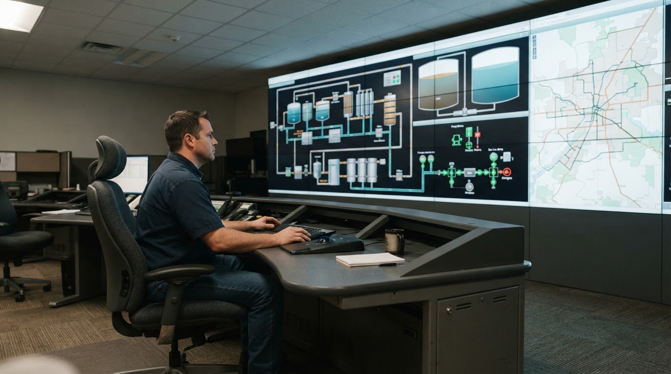
A room’s layout can sharpen decisions or slow them down. Effective water utility control room design aligns operator positions, ergonomic consoles, environmental controls, and display sightlines with the work teams need to do. This keeps critical information visible and accessible as conditions change, while clarifying which systems operators must monitor, what teams need to share, and what to elevate during an event.
Utility teams rely on clear operational information and coordinated responses. But fragmented systems, data silos, and alerts that do not escalate automatically can leave operators piecing together the operating picture. Most control rooms already have screens; the challenge is deciding what appears on them and surfacing information that needs attention. This guide explains how workflows, console layouts, ergonomics, environmental controls, and display placement work together, and how system integration supports situational awareness across water and energy operations.
Key Takeaways
- Plan operator positions around the work: decide which tasks need focused attention and where teams must collaborate.
- Align console configuration, sightlines, circulation, and equipment access with operators’ real workflows.
- Use lighting zones, glare control, acoustics, and temperature planning to support focus during extended monitoring.
- Set display placement and content priorities so operators can see essential information without losing the broader operating picture.
- Connect siloed applications and data feeds to support a coordinated view and clearer escalation during operational events.
WHAT IS CONTROL ROOM DESIGN?
Control room design organizes people, systems, and information around operational decisions. For water utilities, the layout should connect operator tasks with the data and colleagues needed to respond.
Operator-Centered Room Layout
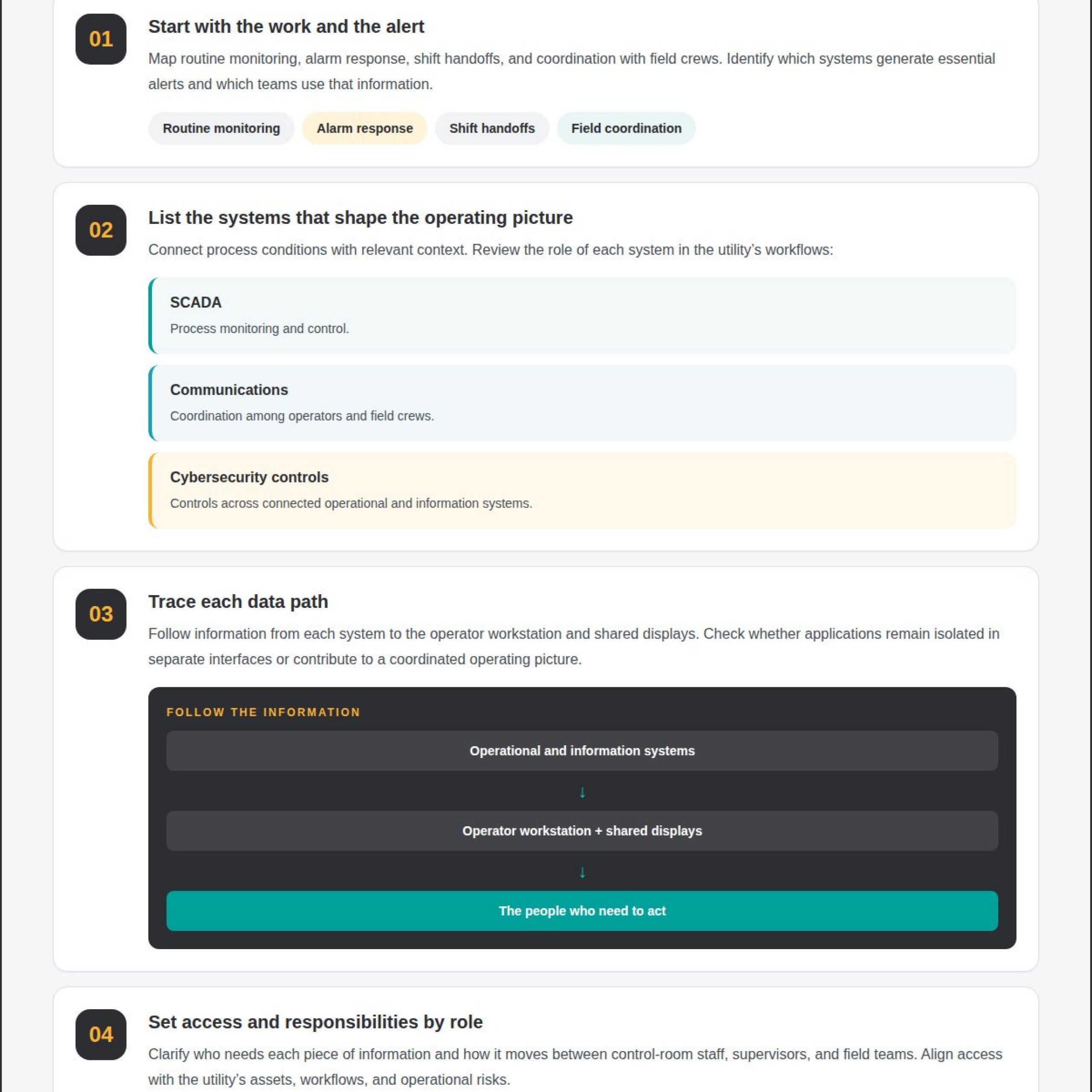
Start with the work, then place each console and workstation to support it. Map routine monitoring, alarm response, shift handoffs, and coordination with field crews before settling the room layout. A focused operator position can support detailed SCADA monitoring, while a shared team area can support incident coordination. Position supervisors so they can communicate with operators without obstructing screens or travel routes.
Map routes between consoles, entrances, briefing areas, and shared resources. Operators should be able to reach colleagues quickly without crossing active work zones or blocking equipment access. Trace a response from the initial alert through assessment, escalation, and handoff. This reveals whether the layout supports collaboration or forces staff to leave their workstations to share essential information.
A water utility control room design should account for how operators use controls and displays during demanding periods. Keep frequently used information within a natural viewing area and arrange consoles for direct team communication. Include equipment access and future reconfiguration in the plan, so maintenance and operational changes do not undermine the layout.
Operational Technology and IT Integration
Operational technology (OT) supports processes such as water treatment and distribution, while information technology (IT) supports business data and communications. Integration helps operators connect process conditions with relevant context. Begin by identifying which systems generate essential alerts, which teams use the information, and where it needs to be visible.
Then map the data path from each system to the operator workstation and shared displays. Define access by role and clarify how information moves between control-room staff, supervisors, and field teams. A useful design review checks whether systems remain isolated in separate interfaces or contribute to a coordinated operating picture. Activu’s manufacturing process control approach addresses the need to bring operational information into a more unified view.
Plan for change as well as integration. Document system dependencies, equipment access, and the operational steps required when an application is updated or unavailable. This makes the relationship between IT and OT clear to the people who operate and maintain the environment.
Control Room Systems and Case Study
A water utility control room should bring together SCADA for process monitoring and control, communications for coordination among operators and field crews, and cybersecurity controls across connected operational and information systems. Set information flows and access according to the utility’s assets, workflows, and operational risks. Keep essential status, alarms, and response information accessible to the people responsible for decisions.
The Georgia System Operations Corporation case study offers a reference point for control-room planning. Use it to structure a review: identify operating roles, map the systems each role needs, and trace how information reaches decision-makers. The case study can inform questions about room organization and coordination, but it does not replace analysis of a utility’s specific workflows.
Incident history also shows why alarm interpretation needs attention. The National Transportation Safety Board estimated the total release at 843,444 gallons of crude oil. For control-room planning, the practical step is to examine how alarms appear, how operators distinguish related conditions, and how escalation reaches the right team. Clear routes, coordinated systems, and purposeful console placement help keep that response connected.
Spatial, ergonomic, environmental, and functional design
For ergonomic planning, ISO 11064 provides an international framework, and Part 1 is a 2000 standard. Key design requirements include accessible workstations, clear circulation, suitable sightlines, and environmental controls; OSHA and EPA obligations should be assessed against the utility’s operations and applicable requirements.
Ergonomics and Fatigue Reduction
Ergonomic planning reduces avoidable strain during extended monitoring. Begin by testing workstation height, monitor placement, chair clearance, and reach to frequently used controls. Height-adjustable sit-stand workstations let operators change posture while maintaining access to the console. Check knee space for the 95th percentile of male operators, as recommended in the design guidance.
For 24/7 environments, evaluate the workstation as operators will use it during long shifts, not only during a brief walkthrough. Position essential displays within a comfortable viewing range, and keep routine controls within easy reach. Review the complete task sequence, including alarm acknowledgment and handoffs, to identify repetitive movements or awkward reaches that can add fatigue.
Functional design also accounts for access to power, data, and equipment. Preserve chair clearance and circulation around each workstation, then test whether operators can move between tasks without obstructing colleagues. These practical checks connect console dimensions to the work performed at each position.
ISO 11064 Ergonomic Principles
ISO 11064 addresses ergonomic design for control centers. Its principles support a systematic review of operator tasks, workstation configuration, information presentation, and the wider room environment. Use the standard as a design framework, then compare proposed arrangements with actual operating procedures and team roles.
For example, map who monitors each process, who coordinates a response, and where supervisors need visibility. Use that workflow to assess console orientation, shared-display sightlines, and movement between work areas. ISO 11064, Part 1, is referenced as a 2000 standard; applying its ergonomic focus means evaluating people, tasks, and equipment together.
Document the review, including task requirements, workstation adjustments, access needs, and the reasons for console placement. This gives teams a practical basis for assessing whether an advanced control room remains functional as procedures or staffing patterns change.
Standards and Design Requirements
OSHA and EPA requirements relate to workplace and environmental obligations, while ISO 11064 addresses control-center ergonomics. A room layout alone does not establish compliance. Identify the utility’s applicable obligations, then coordinate the design review with operational, facilities, and safety responsibilities.
Translate those requirements into checks for circulation, equipment access, lighting, acoustics, and operator comfort. For instance, confirm that chairs can move freely, operators can reach controls without strain, and equipment remains serviceable. The recommended control-room relative humidity is 45-65%; environmental planning should incorporate that range alongside temperature and airflow considerations.
Use a documented review to connect each requirement to a design decision and responsible function. Utilities developing water and energy operations can use this approach to align operator needs with functional room planning.
Lighting, acoustics, temperature, and glare control
Environmental controls affect how clearly operators read displays and communicate during demanding shifts. Plan lighting, sound, temperature, and finishes alongside console work areas.
Lighting and Surface Reflectance
Surface reflectance affects visual comfort across the room. Design guidance recommends ceiling reflectance of 0.8 or greater, wall reflectance of 0.5 to 0.6, and carpet reflectance of 0.2 to 0.3. These values help teams compare finishes and manage how room lighting reaches workstations and displays.
For tile, the stated recommended reflectance value is 0.25 to 0.15. Review samples under the room’s planned lighting, rather than relying on appearance in a showroom. This step can reveal reflections from floors, desks, and other surfaces that compete with console information.
Temperature also affects the working environment. The recommended ambient temperature is between 70 and 72 degrees F. Coordinate that target with lighting and room finishes, then assess conditions at operator positions instead of relying only on a single room reading.
Review acoustics deliberately. Equipment noise, conversations, and reverberation can distract operators during alarm assessment or coordination. Identify likely noise sources and assess their position relative to workstations and briefing areas. A quieter console zone supports concentration while preserving clear communication among teams.
Direct and Indirect Lighting
Separate direct task lighting from indirect ambient lighting. Put each on its own dimmable zone so operators can adjust their work area without changing the entire room. For example, an operator reviewing detailed process information may need different task lighting from colleagues attending a briefing.
Divide room lighting into independently controlled zones instead of putting all fixtures on one switch. Keep lights in front of a control room video wall on a separate zone to limit washout. This lets operators adjust nearby lighting while retaining control over the room’s overall brightness.
Plan controls around operational use. Place dimmers within reach of work areas, then test settings from seated and standing positions. Include task lighting in the workstation review: poorly aimed fixtures can create bright reflections across displays or paperwork.
Glare Management
Glare and low contrast can make visual information harder to interpret. U.S. Nuclear Regulatory Commission human factors evaluations have identified both as contributors to operator error in nuclear control rooms. Apply this concern to utility planning by checking sightlines, light sources, and screen visibility from each operating position.
Assess the room at different times and under each lighting setting. Look for reflections from windows, polished surfaces, and fixtures across console displays. Adjust fixture placement, dimming zones, and finishes where reflections interfere with reading. The stated lighting level in front of a control room display wall is greater than 40 foot-candles, so evaluate that area as part of the full lighting plan.
Finish with an operator walkthrough. Have staff read typical displays from their assigned positions, adjust task lighting, and identify glare or acoustic distractions. Record findings by workstation, then revise the lighting zones or room layout before finalizing the design.
Monitor placement, sightlines, and video walls
Operators need to interpret process data without losing sight of related alerts or team activity. Identify which displays support individual tasks, which information should be shared, and where operators sit during routine monitoring and incident response.
Position workstation monitors at or just below eye level, within each operator’s natural field of view. This reduces repeated head movement between the console and displays elsewhere in the room. Test visibility from the actual seated workstation, since console height and viewing angle matter. Then check whether a standing operator can still see essential information clearly.
A shared display should support collaboration, not become the only place to find critical information. Map sightlines from every operating position, supervisor station, and briefing area. Check for views blocked by consoles, columns, doorways, or people moving through the room. Operators on different shifts should have consistent access to the information they need, even as staffing and work positions change.
Set viewing distance and content requirements before choosing display technology. Room size, viewing positions, content type, budget, and long-term service expectations all affect selection. For an LED video wall, pixel pitch influences the detail visible at different distances. A smaller pixel pitch can support sharper detail at closer range, but assess it against the content, viewing positions, service needs, and budget.
Plan the wall’s dimensions around operator sightlines rather than the available wall area alone. One design recommendation places the lowest screens about 48-52 inches above the floor and leaves 6-8 inches between the top row and ceiling. Treat these as planning reference points, then test visibility from consoles and standing positions before finalizing placement.
Display technology also needs to match operating hours. Control-room LCD panels are not made for 24×7 operation, and not all front projectors are rated for 24×7 environments. Compare the operating schedule with the technology’s service expectations and replacement plan. Consider how teams will access equipment for maintenance without obstructing active workstations or interrupting operational visibility.
Finish with a practical sightline test. Show representative process displays and incident information, then ask operators at each console to locate key details. Check the view under normal lighting and during shift handoffs. If users must turn away, leave a workstation, or search multiple displays for related information, revise placement and content priorities before finalizing the room design.
Control-room solutions for water and energy utilities
Water and energy utilities need control rooms that connect operational systems, people, and response workflows. Modernization should address fragmented information, resilience, and changing operational demands together.
Project Cost and Planning
The cost of building or renovating a control room depends on project scope, existing infrastructure, integration needs, room changes, and lifecycle expectations. The price depends on the case and is provided after a quote request. Identify operational pain points and strategic goals first, then define requirements, assess infrastructure, plan the design, and prepare commissioning around system dependencies.
Commissioning should test that systems, information flows, and operator workflows work together before the room enters operation. Include workforce training and change management so teams can adopt updated technology and procedures. Project timelines depend on scope, dependencies, and the transition plan, so sequence design, integration, testing, and training to support operational continuity.
For utilities assessing modernization priorities, utility control-room planning can help connect operational needs with the broader design.
Backup Power and Redundancy
Plan backup power around the systems operators need to maintain visibility and coordinate a response. Identify critical loads, including control interfaces, communications, and information displays, then document how each behaves during a power interruption. Review system dependencies so backup power does not support equipment that has lost its required network or data connection.
Map likely failure points across power, communications, and operational technology. Define which functions need continuity, how operators will recognize a failure, and what alternative workflow they should follow. Test the planned response during commissioning, and keep equipment access and serviceability in view.
Design Risks and Common Mistakes
Common design risks include siloed applications, limited interoperability, insufficient room for expansion, and maintenance that disrupts operations. Assess existing infrastructure and operational pain points before selecting technology. Plan for open standards and APIs where they support data exchange, and allow equipment to be serviced or expanded without opening finished walls.
Physical security and access control should reflect the utility’s security policies and operational roles. Define who may enter controlled areas, how access is managed, and how authorized visitors are handled. Coordinate these procedures with room circulation so security measures do not obstruct emergency movement or equipment service.
Do not treat installation as the finish line. A design that overlooks training, change management, or operator workflows can leave teams struggling to adopt new processes. Review the operating picture across water and energy functions, identify what must be shared during an event, and test escalation paths. These steps strengthen situational awareness and operational efficiency while reducing avoidable strain on staff.
Activu Corporation: Video Wall Systems
Activu Corporation helps water and energy teams connect operational information through Video Wall Systems, Application Integration, and the vis/ability Platform. Fragmented applications, information silos, and missing automatic escalation can delay a shared understanding during an incident.
Most control rooms already have the screens. What they’re missing is the layer that decides what goes on them – and escalates automatically when something needs attention. vis/ability is an operational intelligence layer that surfaces through the video wall. It serves as the central hub where connected tools flow together, helping teams see the answer where it appears and focus on the decisions at hand.
Teams can use vis/ability across command centers, remote locations, conference rooms, breakout rooms, huddle rooms, and mobile devices. To discuss control-room needs with Activu Corporation, contact the team.
Set the Next Design Decision in Motion
Turn operational priorities into a design brief your teams can use. Identify the decisions operators must make, the information those decisions require, and the people who need a shared view. This gives water utility control room design a clear operational purpose and helps align future changes with real workflows.
Activu Corporation offers Video Wall Systems, the vis/ability Platform, and Event-Driven Situational Awareness. The platform brings operational information together so teams can focus on essential signals and apply informed judgment as conditions change.
Use your design priorities to start a focused conversation about the operational picture your teams need. Contact Activu Corporation to discuss the next step, and move forward with greater clarity.
Frequently Asked Questions
Why are control rooms essential?
Control rooms give utility teams a place to interpret operational conditions and coordinate decisions. For example, when a water treatment alert coincides with a communication from a field crew, operators need to connect both inputs and determine who responds. A shared operating environment helps teams maintain context across monitoring, escalation, and response. Its value depends on whether people can access relevant information and act on it together.
How should control room layout, consoles, and sightlines be planned for water utilities?
Plan around actual tasks and test the arrangement against a realistic operating scenario. Have operators trace a sequence such as reviewing a process alert, consulting related information, and coordinating with a supervisor. Note where they must turn, move, or interrupt someone to complete each step. Use these observations to adjust console orientation and shared-display visibility before finalizing the room plan.
What ergonomic standards apply to water utility control room workstations?
ISO 11064 is an international standard for ergonomic control-center design, and its principles can guide workstation reviews. Assess each position with the operators who will use it, including reach to controls, screen readability, posture changes, and access during routine tasks. A practical evaluation should include different operator body dimensions and duties, then record adjustments needed for comfortable, functional use across shifts.
How should lighting, acoustics, HVAC, and air quality be designed in a control room?
Design these conditions as a coordinated environment, then evaluate them from occupied workstations. HVAC planning should control temperature and air movement without directing distracting drafts across operators. Recommended air movement is less than 4 inches to 6 inches per second. Review ventilation and air quality as part of facilities planning, while checking whether equipment noise or room reverberation masks spoken coordination or draws attention from active tasks.
What SCADA, communications, and cybersecurity systems should a water utility control room include?
Include SCADA for process monitoring and control, communications for coordination among operators and field crews, and cybersecurity controls across connected operational and information systems.